Tag: cisco
EIGRP common ccna questions/issues, solved
EIGRP common ccna questions/issues, solved
The network of this simulation lab the routers R1, R2 and R3 with serial links. R2 and R3 are connected to the switches SW3 and SW4, respectively. SW3 and SW4 are also connected to the routers R4 and R5 and R4 and R5 are connected to the switches SW5 and SW6, respectively. The EIGRP routing protocol is configured.

It is important to know how to troubleshoot and resolve the EIGRP issues between the various routers.
For example,
a) Which path does traffic take from R1 to R5?
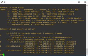
To answer to this question, verifying the routing table on R1 as you can see is
by D 192.168.5.0/24 [90/2174976] via 172.16.3.5, 00:03:05, Serial5/1
[90/2174976] via 172.16.2.5, 00:03:05, Serial5/0
The traffic is equally load-balanced over R2 and R3
R1#
R1#show ip route eigrp
…
10.0.0.0/8 is variably subnetted, 3 subnets, 2 masks
D 10.10.20.0/24
[90/28416] via 172.16.3.10, 00:31:16, GigabitEthernet4/0
172.16.0.0/16 is variably subnetted, 8 subnets, 3 masks
D 172.16.4.0/24 [90/2172416] via 172.16.3.5, 00:03:06, Serial5/1
[90/2172416] via 172.16.2.5, 00:03:06, Serial5/0
D 192.168.4.0/24 [90/2174976] via 172.16.3.5, 00:03:05, Serial5/1
[90/2174976] via 172.16.2.5, 00:03:05, Serial5/0
D 192.168.5.0/24 [90/2174976] via 172.16.3.5, 00:03:05, Serial5/1
[90/2174976] via 172.16.2.5, 00:03:05, Serial5/0
…
b)Router R6 does not form an EIGRP neighbor relationship correctly with router R1
Versification to make:
1- Interfaces connected R1 and R6 are line “up” and protocol “up”
2- Check if is there any neighbor
R6#show ip eigrp neighbors
Is not showing any neighbor at all.
3- Verifying eigrp configuration on R6 and R1
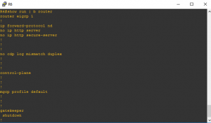
R6#show run | b router
router eigrp 1
!
From the last show run | b router,
the network command is missing on the router R6 that is the cause to the router R6 does not form an EIGRP neighbor relationship correctly with router R1.
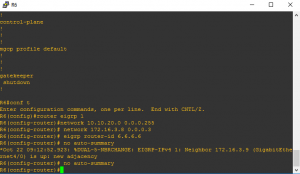
By entering on router R6
R6#conf t
Enter configuration commands, one per line. End with CNTL/Z.
R6(config)#router eigrp 1
R6(config-router)#network 10.10.20.0 0.0.0.255
R6(config-router)# network 172.16.3.8 0.0.0.3
R6(config-router)# eigrp router-id 6.6.6.6
*Oct 22 09:12:52.923: %(GigabitEthernet4/0) is up: new adjacency
R6(config-router)# no auto-summary
c) Mismatch EIGRP AS number issue.
R4 has been incorrectly configured to be in another AS, so it does not peer with R5 that will cause the loopback interfaces on R4 with the IP addresses of 10.4.4.4 /32, 10.4.4.5/32. and
10.4.4.6/32 are not appearing in the routing table of R5
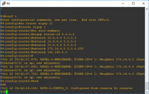
Verifying the eigrp configuration on R4,
R4#show run | b router
router eigrp 11
network 10.4.4.4 0.0.0.0
network 10.4.4.5 0.0.0.0
network 10.4.4.6 0.0.0.0
network 172.16.4.0 0.0.0.255
network 192.168.4.0
eigrp router-id 4.4.4.4
!
The ASN on the router R4 is 11 and it should be 1. Changing the ASN from 11 to 1 the the loopback interfaces on R4 with the IP addresses of 10.4.4.4 /32, 10.4.4.5/32. and 10.4.4.6/32 will appear in the routing table of R5
Verifying the routing table on R5
R5#show ip route eigrp
10.0.0.0/8 is variably subnetted, 6 subnets, 2 masks
D 10.4.4.4/32 [90/156160] via 172.16.4.1, 00:00:34, FastEthernet0/0
D 10.4.4.5/32 [90/156160] via 172.16.4.1, 00:00:34, FastEthernet0/0
D 10.4.4.6/32 [90/156160] via 172.16.4.1, 00:00:34, FastEthernet0/0
D 10.10.10.0/24 [90/2174976] via 172.16.4.4, 00:53:50, FastEthernet0/0
[90/2174976] via 172.16.4.2, 00:53:50, FastEthernet0/0
D 10.10.20.0/24 [90/2175232] via 172.16.4.4, 00:15:38, FastEthernet0/0
[90/2175232] via 172.16.4.2, 00:15:38, FastEthernet0/0
172.16.0.0/16 is variably subnetted, 7 subnets, 3 masks
D 172.16.2.4/30 [90/2172416] via 172.16.4.2, 00:53:50, FastEthernet0/0
D 172.16.3.4/30 [90/2172416] via 172.16.4.4, 00:53:50, FastEthernet0/0
D 172.16.3.5/32 [90/2684416] via 172.16.4.2, 00:53:50, FastEthernet0/0
D 172.16.3.6/32 [90/2172416] via 172.16.4.4, 01:00:44, FastEthernet0/0
D 172.16.3.8/30 [90/2172672] via 172.16.4.4, 00:53:50, FastEthernet0/0
[90/2172672] via 172.16.4.2, 00:53:50, FastEthernet0/0
D 192.168.4.0/24 [90/30720] via 172.16.4.1, 00:00:33, FastEthernet0/0
R5#
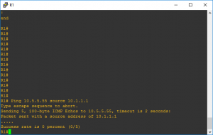
d)The network statement is missing on R1.
R1# Ping 10.5.5.55 source 10.1.1.1
Type escape sequence to abort.
Sending 5, 100-byte ICMP Echos to 10.5.5.55, timeout is 2 seconds:
Packet sent with a source address of 10.1.1.1
…..
Success rate is 0 percent (0/5)
R1#
Verifying the eigrp configuratuion on router R1
R1#show run | b router
router eigrp 1
network 10.10.10.0 0.0.0.255
network 172.16.2.4 0.0.0.3
network 172.16.3.4 0.0.0.3
network 172.16.3.8 0.0.0.3
eigrp router-id 1.1.1.1
!
Is not there any network command for network 10.1.1.1. To configure that
R1#conf t
Enter configuration commands, one per line. End with CNTL/Z.
R1(config)#router eigrp 1
R1(config-router)#network 10.1.1.1 0.0.0.0
Now trying to ping 10.5.5.55 from the source 10.1.1.1 again,
R1#Ping 10.5.5.55 source 10.1.1.1
Type escape sequence to abort.
Sending 5, 100-byte ICMP Echos to 10.5.5.55, timeout is 2 seconds:
Packet sent with a source address of 10.1.1.1
!!!!!
Success rate is 100 percent (5/5), round-trip min/avg/max = 20/29/40 ms
Download now this simulation lab done with GNS3 to prepare or understand how EIGRP is functioning.
[download id=”4434″]

