Tag: GNS3
EIGRP common ccna questions/issues, solved
EIGRP common ccna questions/issues, solved
The network of this simulation lab the routers R1, R2 and R3 with serial links. R2 and R3 are connected to the switches SW3 and SW4, respectively. SW3 and SW4 are also connected to the routers R4 and R5 and R4 and R5 are connected to the switches SW5 and SW6, respectively. The EIGRP routing protocol is configured.

It is important to know how to troubleshoot and resolve the EIGRP issues between the various routers.
For example,
a) Which path does traffic take from R1 to R5?
To answer to this question, verifying the routing table on R1 as you can see is
by D 192.168.5.0/24 [90/2174976] via 172.16.3.5, 00:03:05, Serial5/1
[90/2174976] via 172.16.2.5, 00:03:05, Serial5/0
The traffic is equally load-balanced over R2 and R3
R1#
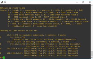
R1#show ip route eigrp
…
10.0.0.0/8 is variably subnetted, 3 subnets, 2 masks
D 10.10.20.0/24
[90/28416] via 172.16.3.10, 00:31:16, GigabitEthernet4/0
172.16.0.0/16 is variably subnetted, 8 subnets, 3 masks
D 172.16.4.0/24 [90/2172416] via 172.16.3.5, 00:03:06, Serial5/1
[90/2172416] via 172.16.2.5, 00:03:06, Serial5/0
D 192.168.4.0/24 [90/2174976] via 172.16.3.5, 00:03:05, Serial5/1
[90/2174976] via 172.16.2.5, 00:03:05, Serial5/0
D 192.168.5.0/24 [90/2174976] via 172.16.3.5, 00:03:05, Serial5/1
[90/2174976] via 172.16.2.5, 00:03:05, Serial5/0
…
b)Router R6 does not form an EIGRP neighbor relationship correctly with router R1
Versification to make:
1- Interfaces connected R1 and R6 are line “up” and protocol “up”
2- Check if is there any neighbor
R6#show ip eigrp neighbors
Is not showing any neighbor at all.
3- Verifying eigrp configuration on R6 and R1
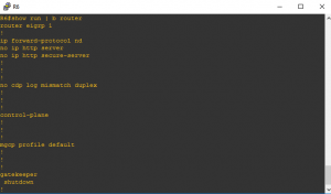
R6#show run | b router
router eigrp 1
!
From the last show run | b router,
the network command is missing on the router R6 that is the cause to the router R6 does not form an EIGRP neighbor relationship correctly with router R1.
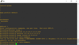
By entering on router R6
R6#conf t
Enter configuration commands, one per line. End with CNTL/Z.
R6(config)#router eigrp 1
R6(config-router)#network 10.10.20.0 0.0.0.255
R6(config-router)# network 172.16.3.8 0.0.0.3
R6(config-router)# eigrp router-id 6.6.6.6
*Oct 22 09:12:52.923: %(GigabitEthernet4/0) is up: new adjacency
R6(config-router)# no auto-summary
c) Mismatch EIGRP AS number issue.
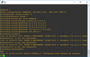
R4 has been incorrectly configured to be in another AS, so it does not peer with R5 that will cause the loopback interfaces on R4 with the IP addresses of 10.4.4.4 /32, 10.4.4.5/32. and
10.4.4.6/32 are not appearing in the routing table of R5
Verifying the eigrp configuration on R4,
R4#show run | b router
router eigrp 11
network 10.4.4.4 0.0.0.0
network 10.4.4.5 0.0.0.0
network 10.4.4.6 0.0.0.0
network 172.16.4.0 0.0.0.255
network 192.168.4.0
eigrp router-id 4.4.4.4
!
The ASN on the router R4 is 11 and it should be 1. Changing the ASN from 11 to 1 the the loopback interfaces on R4 with the IP addresses of 10.4.4.4 /32, 10.4.4.5/32. and 10.4.4.6/32 will appear in the routing table of R5
Verifying the routing table on R5
R5#show ip route eigrp
10.0.0.0/8 is variably subnetted, 6 subnets, 2 masks
D 10.4.4.4/32 [90/156160] via 172.16.4.1, 00:00:34, FastEthernet0/0
D 10.4.4.5/32 [90/156160] via 172.16.4.1, 00:00:34, FastEthernet0/0
D 10.4.4.6/32 [90/156160] via 172.16.4.1, 00:00:34, FastEthernet0/0
D 10.10.10.0/24 [90/2174976] via 172.16.4.4, 00:53:50, FastEthernet0/0
[90/2174976] via 172.16.4.2, 00:53:50, FastEthernet0/0
D 10.10.20.0/24 [90/2175232] via 172.16.4.4, 00:15:38, FastEthernet0/0
[90/2175232] via 172.16.4.2, 00:15:38, FastEthernet0/0
172.16.0.0/16 is variably subnetted, 7 subnets, 3 masks
D 172.16.2.4/30 [90/2172416] via 172.16.4.2, 00:53:50, FastEthernet0/0
D 172.16.3.4/30 [90/2172416] via 172.16.4.4, 00:53:50, FastEthernet0/0
D 172.16.3.5/32 [90/2684416] via 172.16.4.2, 00:53:50, FastEthernet0/0
D 172.16.3.6/32 [90/2172416] via 172.16.4.4, 01:00:44, FastEthernet0/0
D 172.16.3.8/30 [90/2172672] via 172.16.4.4, 00:53:50, FastEthernet0/0
[90/2172672] via 172.16.4.2, 00:53:50, FastEthernet0/0
D 192.168.4.0/24 [90/30720] via 172.16.4.1, 00:00:33, FastEthernet0/0
R5#
d)The network statement is missing on R1.
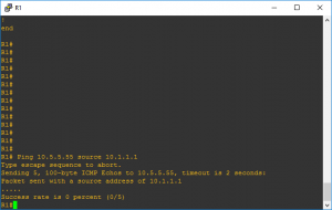
R1# Ping 10.5.5.55 source 10.1.1.1
Type escape sequence to abort.
Sending 5, 100-byte ICMP Echos to 10.5.5.55, timeout is 2 seconds:
Packet sent with a source address of 10.1.1.1
…..
Success rate is 0 percent (0/5)
R1#
Verifying the eigrp configuratuion on router R1
R1#show run | b router
router eigrp 1
network 10.10.10.0 0.0.0.255
network 172.16.2.4 0.0.0.3
network 172.16.3.4 0.0.0.3
network 172.16.3.8 0.0.0.3
eigrp router-id 1.1.1.1
!
Is not there any network command for network 10.1.1.1. To configure that
R1#conf t
Enter configuration commands, one per line. End with CNTL/Z.
R1(config)#router eigrp 1
R1(config-router)#network 10.1.1.1 0.0.0.0
Now trying to ping 10.5.5.55 from the source 10.1.1.1 again,
R1#Ping 10.5.5.55 source 10.1.1.1
Type escape sequence to abort.
Sending 5, 100-byte ICMP Echos to 10.5.5.55, timeout is 2 seconds:
Packet sent with a source address of 10.1.1.1
!!!!!
Success rate is 100 percent (5/5), round-trip min/avg/max = 20/29/40 ms
Download now this simulation lab done with GNS3 to prepare or understand how EIGRP is functioning.
[download id=”4434″]
Configure and schedule IP SLA
Configure and schedule IP SLA
The example is how configure IP SLA 13 and 14 on a Cisco router, version of Cisco IOS Software, 7200 Software (C7200-ADVENTERPRISEK9-M), Version 15.2(4) using GNS3
R3(config)#ip sla 13
R3(config-ip-sla)#?
IP SLAs entry configuration commands:
dhcp DHCP Operation
dns DNS Query Operation
ethernet Ethernet Operations
exit Exit Operation Configuration
ftp FTP Operation
http HTTP Operation
icmp-echo ICMP Echo Operation
icmp-jitter ICMP Jitter Operation
mpls MPLS Operation
path-echo Path Discovered ICMP Echo Operation
path-jitter Path Discovered ICMP Jitter Operation
tcp-connect TCP Connect Operation
udp-echo UDP Echo Operation
udp-jitter UDP Jitter Operation
voip Voice Over IP Operation
R3(config-ip-sla)#icmp-echo 172.14.0.3 source-ip 192.168.2.1
R3(config-ip-sla)#frequency 300
R3(config-ip-sla)#ip sla schedule 13 life forever start-time now
Configure the IP SLA 14
R3(config)#ip sla 14
R3(config-ip-sla)#icmp-echo 192.168.16.1 source-ip 192.168.2.1
R3(config-ip-sla)#ip sla schedule 14 life forever start-time now
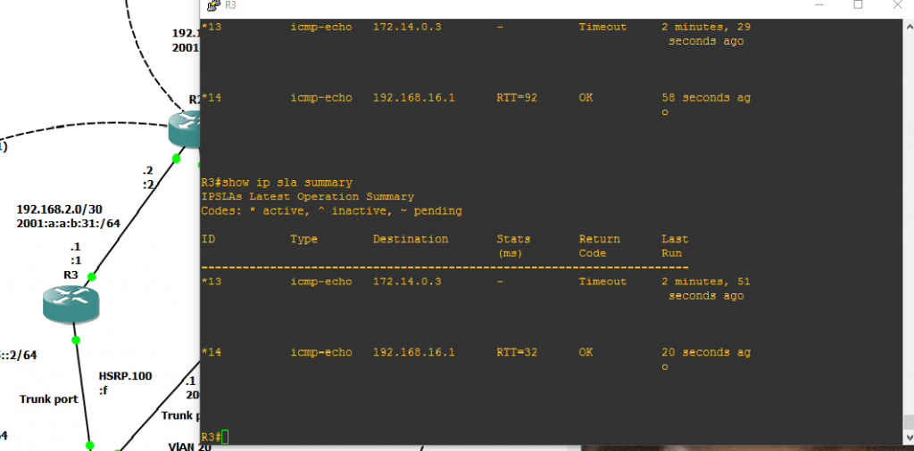
Verify IP SLA
R3#show ip sla summary
IPSLAs Latest Operation Summary
Codes: * active, ^ inactive, ~ pending
ID Type Destination Stats Return Last
(ms) Code Run
———————————————————————–
*13 icmp-echo 172.14.0.3 – Timeout 2 minutes, 57 seconds ago
*14 icmp-echo 192.168.16.1 RTT=76 OK 25 seconds ago
[download id=”4264″]
Lab, simulation, configuring PPPoE client&server side GNS3
Lab, simulation, configuring PPPoE client&server side GNS3
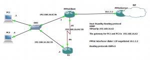
Step 1 Configuring PPPoE Server side
PPPoEServer#conf t
Enter configuration commands, one per line. End with CNTL/Z.
PPPoEServer(config)#bb?
bba-group
PPPoEServer(config)#bba-group ?
pppoe PPPoE type
PPPoEServer(config)#bba-group pppoe ?
WORD BBA Group name
global PPPoE global group
PPPoEServer(config)#bba-group pppoe UKgoodbyeGroup
PPPoEServer(config-bba-group)#
*Sep 6 11:41:03.807: %LINEPROTO-5-UPDOWN: Line protocol on Interface Virtual-Access1, changed state to up
PPPoEServer(config-bba-group)#
*Sep 6 11:41:03.815: %LINK-3-UPDOWN: Interface Virtual-Access1, changed state to up
PPPoEServer(config-bba-group)#virtual-template ?
Virtual Template interface number
PPPoEServer(config-bba-group)#virtual-template 26
PPPoEServer(config-bba-group)#?
BBA Group configuration commands:
control-packets PPPoE control packets related configuration
default Set a command to its defaults
exit Exit from BBA Group configuration mode
limit limit contents of pppoe control messages
mac-address Set mac address
nas-port Specific format for nas-port
nas-port-id Specific format for nas-port-id
no Negate a command or set its defaults
pado PADO delay options
pppoe PPPoE server selection configuration
service Services to be associated with this group
sessions BBA session commands
tag Configure processing options for a tag
vendor-tag PPPoE Vendor Specific Tag
virtual-template BBA virtual template command
PPPoEServer(config-bba-group)#sessions per-mac limit 2
PPPoEServer(config-bba-group)#exit
PPPoEServer(config)#interface virtual-template ?
Virtual-Template interface number
PPPoEServer(config)#interface virtual-template 26
PPPoEServer(config-if)#ip address 10.1.3.1 255.255.255.0
Authentication:
PPPoEServer(config-if)#ppp authentication chap callin
PPPoEServer(config-if)#peer default ip address ?
dhcp Use DHCP proxy client mechanism to allocate a peer IP address
dhcp-pool Use local DHCP pools to allocate a peer IP address
pool Use IP pool mechanism to allocate a peer IP address
PPPoEServer(config-if)#peer default ip address pool EUPool
PPPoEServer(config)#ip local pool EUPool 10.1.3.2 10.1.3.254
You must to create a username and password on the client side too.
PPPoEServer(config)#username Brexit password fromEU
Associate the interface of the server side:
PPPoEServer(config)#interface g4/0
PPPoEServer(config-if)#no ip address
PPPoEServer(config-if)#pppoe enable group UKgoodbyeGroup
PPPoEServer(config-if)#no shutdow
PPPoEServer(config-if)#
Step 2 Configuring PPPoE client side
PPPoEClient(config)#interface dialer 1
PPPoEClient(config-if)#dialer pool 1
PPPoEClient(config-if)#encapsulation ppp
The authentication from to client side to pppoe server, will as username “Brexit” and password “fromEU”.
PPPoEClient(config-if)#ppp chap hostname Brexit
PPPoEClient(config-if)#ppp chap password fromEU
PPPoEClient(config-if)#ip address negotiated
The MTU is 1500-8= 1492, because the PPP header adds 8 bytes of overhead to each frame.
PPPoEClient(config-if)#mtu ?
MTU size in bytes
PPPoEClient(config-if)#mtu 1492
PPPoEClient(config-if)#exi
PPPoEClient(config)#interface g4/0
PPPoEClient(config-if)#no ip address
PPPoEClient(config-if)#pppoe-client ?
dial-pool-number dialer pool keyword
ppp-max-payload Send PPP Max-Payload tag in PPPoE control packets
PPPoEClient(config-if)#pppoe-client dial-pool-number ?
Dialer pool number
PPPoEClient(config-if)#pppoe-client dial-pool-number 1
PPPoEClient(config-if)#no shutdown
PPPoEClient(config-if)#
The PPPoE session has successfully formed
*Sep 6 12:28:59.347: %DIALER-6-BIND: Interface Vi1 bound to profile Di1
PPPoEClient(config-if)#
*Sep 6 12:28:59.359: %LINK-3-UPDOWN: Interface Virtual-Access1, changed state to up
PPPoEClient(config-if)#
*Sep 6 12:29:00.039: %LINEPROTO-5-UPDOWN: Line protocol on Interface Virtual-Access1, changed state to up
Step 3 Verification
PPPoEClient#show ip interface brief
Interface IP-Address OK? Method Status Protocol
FastEthernet0/0 192.168.16.1 YES manual up up
Serial5/0 192.168.16.65 YES manual up up
Dialer1 10.1.3.2 YES IPCP up up
PPPoEClient#
The show pppoe session shows the session stablished on dialer 1 via GigabitEthernet4/0
PPoEClient#show pppoe session
1 client session
Uniq ID PPPoE RemMAC Port VT VA State
SID LocMAC VA-st Type
N/A 16 ca03.1540.0070 Gi4/0 Di1 Vi1 UP
ca01.0410.0070 UP
PPPoEClient#
Download the GNS3 file for the simulation WAN PPPoE and OSPF as routing protocol
[download id=”4137″]
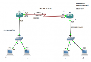
Practice lab Cisco CCNA R&S Serial Multilink and EIGRP Done on GNS3
Practice lab Cisco CCNA R&S Serial Multilink and EIGRP Done on GNS3
It is recommended to GNS3 than pcket Tracer PP multilink.
Step 1 Configuring multilink on router R1
R1(config)#interface multilink 13
R1(config-if)#ip address 192.168.16.2 255.255.255.252
R1(config-if)#ppp multilink
R1(config-if)#ppp multilink group 13
R1(config-if)#no shutdown
1.1 Configuring the interface serial5/0 on Router R1
R1(config)#interface Serial5/0
R1(config-if)#encapsulation ppp
R1(config-if)#ppp multilink
R1(config-if)#ppp multilink group 13
R1(config-if)#no shutdown
1.2 Configuring the interface serial5/1 on router R1
R1(config)#interface Serial5/1
R1(config-if)#encapsulation ppp
R1(config-if)#ppp multilink
R1(config-if)#ppp multilink group 13
R1(config-if)#no shutdown
Now, you should configure the router at other end in that case is the route R2
Step 2 Configuring multilink on router R2
R2(config)#interface multilink 13
R2(config-if)#ip address 192.168.16.2 255.255.255.252
R2(config-if)#ppp multilink
R2(config-if)#ppp multilink group 13
R2(config-if)#no shutdown
2.1 Configuring the interface serial5/0 on Router R2
R2(config)#interface Serial5/0
R2(config-if)#encapsulation ppp
R2(config-if)#ppp multilink
R2(config-if)#ppp multilink group 13
R2(config-if)#no shutdown
2.2 Configuring the interface serial5/1 on router R2
R2(config)#interface Serial5/1
R2(config-if)#encapsulation ppp
R2(config-if)#ppp multilink
R2(config-if)#ppp multilink group 13
R2(config-if)#no shutdown
Verify the multilink on router R1 and R2
R1#show ppp multilink
Multilink13
Bundle name: R2
Remote Endpoint Discriminator: [1] R2
Local Endpoint Discriminator: [1] R1
Bundle up for 00:23:23, total bandwidth 3088, load 1/255
Receive buffer limit 24000 bytes, frag timeout 1000 ms
0/0 fragments/bytes in reassembly list
0 lost fragments, 0 reordered
0/0 discarded fragments/bytes, 0 lost received
0x46 received sequence, 0x46 sent sequence
Member links: 2 active, 0 inactive (max 255, min not set)
Se5/0, since 00:23:23
Se5/1, since 00:23:11
No inactive multilink interfaces
R1#
R2#show ppp multilink
Multilink13
Bundle name: R1
Remote Endpoint Discriminator: [1] R1
Local Endpoint Discriminator: [1] R2
Bundle up for 00:25:42, total bandwidth 3088, load 1/255
Receive buffer limit 24000 bytes, frag timeout 1000 ms
0/0 fragments/bytes in reassembly list
0 lost fragments, 0 reordered
0/0 discarded fragments/bytes, 0 lost received
0x4C received sequence, 0x4C sent sequence
Member links: 2 active, 0 inactive (max 255, min not set)
Se5/0, since 00:25:42
Se5/1, since 00:25:29
No inactive multilink interfaces
R2#
Configuring EIGRP for IPv4 as routing protocol
Configuring EIGRP on router R1
R1#conf t
Enter configuration commands, one per line. End with CNTL/Z.
R1(config)#router eigrp 2
R1(config-router)#network 192.168.16.0 0.0.0.3
R1(config-router)#network 192.168.15.0 0.0.0.255
R1(config-router)#
*Sep 5 13:13:25.831: %DUAL-5-NBRCHANGE: EIGRP-IPv4 2: Neighbor 192.168.16.2 (Multilink13) is up: new adjacency
R1(config-router)#no auto-summary
Configuring EIGRP on router R2
R2#conf t
Enter configuration commands, one per line. End with CNTL/Z.
R2(config)#router eigrp 2
R2(config-router)#network 192.168.16.0 0.0.0.3
R2(config-router)#
*Sep 5 13:11:35.811: %DUAL-5-NBRCHANGE: EIGRP-IPv4 2: Neighbor 192.168.16.1 (Multilink13) is up: new adjacency
R2(config-router)#network 192.168.14.0 0.0.0.255
R2(config-router)#no auto-summary
R2(config-router)#end
Verifying the routing table
Codes: L – local, C – connected, S – static, R – RIP, M – mobile, B – BGP
D – EIGRP, EX – EIGRP external, O – OSPF, IA – OSPF inter area
N1 – OSPF NSSA external type 1, N2 – OSPF NSSA external type 2
E1 – OSPF external type 1, E2 – OSPF external type 2
i – IS-IS, su – IS-IS summary, L1 – IS-IS level-1, L2 – IS-IS level-2
ia – IS-IS inter area, * – candidate default, U – per-user static route
o – ODR, P – periodic downloaded static route, H – NHRP, l – LISP
+ – replicated route, % – next hop override
Download the lab, EIGRP over multink ppp,[download id=”4128″]

